Forward Annotation
Automatically generate and update layout data without errors based on OrCAD circuits
Back Annotation
Maintain design consistency by reflecting layout changes back to the schematic
Footprint settings
Directly specify the component footprint and easily modify and manage it
DRC
Verification of design errors that may occur during the PCB layout data generation process using OrCAD schematics
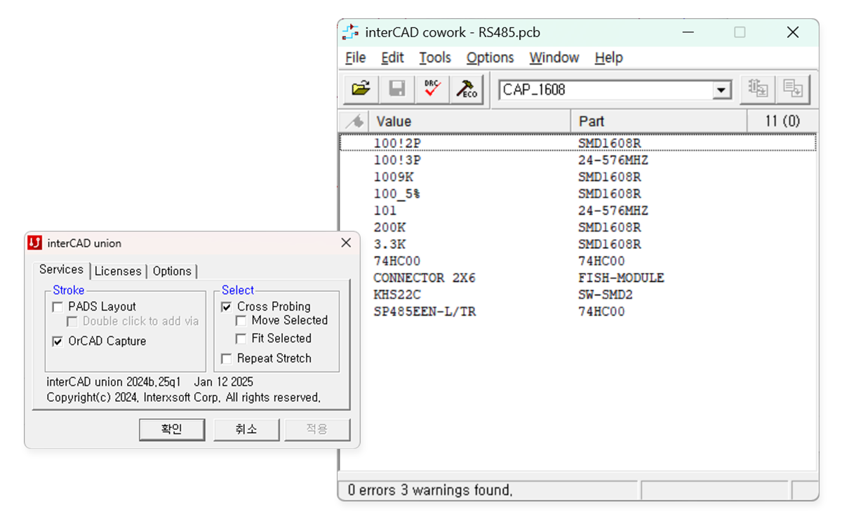
Cross Probing
Support for component/Net click linking between schematic and layout
Excel Netlist to PADS LayoutPro
Create PADS Layout data, update change information, and support error verification (DRC)
Linkable EDA tools
OrCAD Capture / PADS Layout / Board Station Layout / Xpedition Layout (only cross probing supported)
Placement Block Copy
After placing the same Block once, the remaining Blocks are automatically copied and placed in the same way.
Net Length Report
Automatically reports the length of the selected Trace or the length connected between parts
PADS Layout Automation Features
View more / Repeat Stretch / Trace Junction selection / Mouse Stroke command
Board Station Automation Features
Trace Delay Tune / Real Time Length Report / Trace 45 degrees, Arc batch change / Ref.Des batch inspection / Gerber data automatic generation / Geometry automatic generation
Remove Antenna ViaPro
Batch scan and remove all Antenna Vias present on the entire board.
Create Via at midpointPro
Calculate the midpoint of the Trace Pattern and place the mouse cursor or automatically create a Via at that location.
Trace TunePro
Tune the Net's Trace based on the length set in the Hi-Speed Rule value
Decal and part placement with Excel coordinatesPro
Create libraries or place parts using Excel coordinate data
LGA PAD automatic placementPro
Automatically places components in optimal locations on the LGA PAD based on component connection information
Select Via/Component connected to selected NetPro
Select all Vias and components connected to a Net at once
Linkable EDA tools
OrCAD Capture / PADS Layout / Board Station Layout